ECE3400_Team17
This project is maintained by ECE3400Team17
Milestone 1
Hardware Implementation:
We attached 4 sensors in a horizontal line at the bottom of our robot, two of them being in the middle of the car (S2, S3), and the other two being at relatively marginal area of the robot(S0, S5).
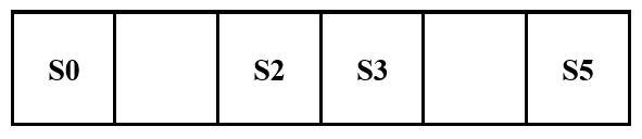
Besides connecting all the sensors to 5v and GND pins, we input the signals of the sensors to arduino’s analog input pins:
- S0 → A0 pin
- S2 → A2 pin
- S3 → A3 pin
- S5 → A5 pin
Following a line:
First step:
We want the car to move following the black line.
The Big Idea:
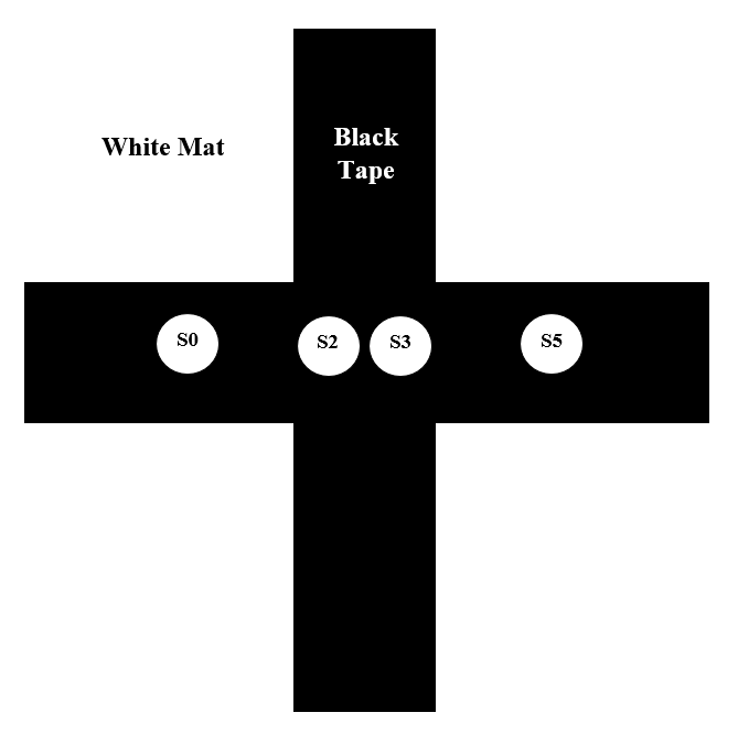
We plan to use 4 sensors to detect the black line. Right middle two of them are responsible for detecting the black line on the way, to make sure it is moving. The left one and the right one are responsible for detecting the turning junction. Then send further instruction to the servos. We develop a logic to adjust its direction.
Preparation:
1. Check all sensors to make sure they work
We connect sensor and Arduino, used a paper to block the light in front of a certain sensor, and find that the parameter changes. When it detects black tape, the value goes high, because the tape will reflect light. When it detects white, the value goes low.
2. Develop the control algorithm
The key in this logic is to make sure the car will automatically change its moving direction slightly so that it can move on line.
- If S2 sees white and S3 sees black, adjust right; (the left sensor moves faster)
- If S3 sees white and S2 sees white, adjust left; (the right sensor moves faster)
- If S2 and S3 both sees black, move forward; (the right and the left sensor move in the same speed)
3. Based on the work done in number 2, we successfully made the car follow the line
- Video of the Robot following a strainght black line:
- Video of the Robot following a curved black line:
The code is as follow:
#include <Servo.h>
// instantiate the 2 servos
Servo servoL;
Servo servoR;

// instantiate the 2 IR sensors
int s2 = A2;
int s3 = A3;

int val2;
int val3;

void setup(){
  Serial.begin(9600);
  servoL.attach(10);
  servoR.attach(11);
}

void loop(){
  // read in values from sensors
  val2 = analogRead(s2);
  val3 = analogRead(s3);

  // if both sensors are on Black
  if ((val2>500)&&(val3>500)){
    // move forward
    servoL.write(120);
    servoR.write(60);
  }

  // if s3 is on White
  else if ((val3<500)){
    // turn Right
    servoL.write(90);
    servoR.write(60);
  }

  // if s2 is on White
  else if((val2<500)){
    // turn Left
    servoL.write(120);
    servoR.write(90);
  }

  else{
    // stop
    servoL.write(90);
    servoR.write(90);
  }
}
Driving in a figure 8:
Basic sub-routines for driving in a figure 8:
1. Crossline detection:
For the grid on which our robot moves, the robot would turn 90 degrees at the crossroad points to draw a figure 8. Hence how to detect the place to turn is the first fundamental sub-routine we need to design. When the robot comes across a crossline, all of the sensors lined up at the bottom of the robot will be on the black tapes. That is to say, if all sensors have a very high input value, we make the robot start to rotate.
2. Turning 90 degrees:
To make the robot turn 90 degrees, we basically used the delay method. We make the two wheels turn in opposite direction for a small amount of time to rotate the robot for a certain angle. The rotating time is controlled by the time we delay, and according to our experiments, the robot will rotate 90 degrees when we delay 800 ms.
3. Moving in figure-8 pattern:
The robot will move in a figure 8 if we make the turning direction in a loop shown below:
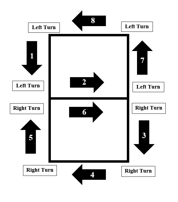
That is :
- 1st Cross Section → turn: Left
- 2nd Cross Section → turn: Left
- 3rd Cross Section → turn: Right
- 4th Cross Section → turn: Right
- 5th Cross Section → turn: Right
- 6th Cross Section → turn: Right
- 7th Cross Section → turn: Left
- 8th Cross Section → turn: Left
Hence, we used a mod function and a counter to help the robot decide which way it should turn (See the details in the code).
Also, since the position of our sensors is at the middle bottom of the robot, so to make sure that the robot would be able to detect the black tapes and keep moving straight after the turning, we make the robot to keep moving forward for 100 ms before turning and after detecting the crossline. Thus the robot would be located front enough to keep itself on the track after turning.
Code for driving in figure 8:
#include <Servo.h>

// motors
Servo servoL;
Servo servoR;

// inputs for sensors
int s0 = A0;
int s2 = A2;
int s3 = A3;
int s5 = A5;

int val0 ;
int val2 ;
int val3 ;
int val5 ;

int thres = 500;
int count = 0;

void setup(){
  count = 0;
  Serial.begin(9600);
  servoL.attach(10);
  servoR.attach(11);
  servoL.write(120);
  servoR.write(60);
  delay(800);
}

// move forward
void goForward(){
  servoL.write(120);
  servoR.write(60);
}

// left turn 90 degrees
void turnLeft(){
  servoL.write(120);
  servoR.write(60);

  delay(100);
  stay();
  servoL.write(0);
  servoR.write(0);

  delay(800);

  servoL.write(90);
  servoR.write(90);
}

// right turn 90 degrees
void turnRight(){
  servoL.write(120);
  servoR.write(60);
  delay(100);
  stay();
  servoL.write(180);
  servoR.write(180);

  delay(800);

  servoL.write(90);
  servoR.write(90);
}

// stop
void stay(){
  servoL.write(90);
  servoR.write(90);


}

// follow the black line
void followLine(){
  // take the sensor reading
  val0 = analogRead(s0);
  val2 = analogRead(s2);
  val3 = analogRead(s3);
  val5 = analogRead(s5);

  // if both sensors are on Black
  if ((val2>500)&&(val3>500)){
    // move forward
    goForward();
  }

  // if s3 is on White
  else if ((val3<500 && val2>500)){
    // turn Right
    servoL.write(90);
    servoR.write(60);
  }

  // if s2 is on White
  else if((val2<500 && val3>500)){
    // turn Left
    servoL.write(120);
    servoR.write(90);
  }

  else{
    // stop
    stay();
  }

}

// make the number 8
void turn_eight(int count) {
  val0 = analogRead(s0);
  val2 = analogRead(s2);
  val3 = analogRead(s3);
  val5 = analogRead(s5);
  if((count%8 >=2) && (count%8 <=5)) {
  	turnRight();
  	val0 = analogRead(s0);
  	val2 = analogRead(s2);
  	val3 = analogRead(s3);
  	val5 = analogRead(s5);

  }
  else {
  	turnLeft();
  	val0 = analogRead(s0);
  	val2 = analogRead(s2);
  	val3 = analogRead(s3);
  	val5 = analogRead(s5);
  }
}


void loop(){
  val0 = analogRead(s0);
  val2 = analogRead(s2);
  val3 = analogRead(s3);
  val5 = analogRead(s5);

  Serial.println(val0);

  // at a crosssection
  if ((val0>thres)&&(val2>thres)&&(val3>thres)&&(val5>thres)){
	stay();
	turn_eight(count);
	count = count +1;
  }

  // otherwise
  else{
	followLine();
  }
}