ECE3400_Team17
This project is maintained by ECE3400Team17
Milestone4
Objective:
The goal of this milestone was to have robot map the maze as it traverses it, as well as indicate the location of the treasures found.
Current overall progress:
Rebuilt the robot: We planned to use a motor with IMU and encoder to replace the servo for our final design. However, the H bridge of the L298N motor controller does not work and the motor could only spin in one direction. As a result, we have to change our motor back to servo, which caused some extra work and made our progress a little bit behind.
We basically have all the separate parts work now for the final competition, and we may need some further working time to implement all of these together
What we have now:
- The robot searching through the maze with algorithm while also sending data to base station’s Arduino for maze drawing.
- The radio communication code to transmit data wirelessly between two Arduino.
- The SPI transmission interface to transmit the robot’s state data from Arduino to FPGA.
- The Verilog code to draw the maze blocks with different color based on the whether the block is a path, wall, or treasure.
Work Distribution For Milestone 4:
- Robot Algorithm: Thinesiya & Alan
- Radio: Yijia & Stephane
- SPI: Alan & Yijia
- VGA Maze Drawing: Peter
Implementing Robot Algorithm in Real Life
We had a MATLAB script from Milestone 3 which allowed us to test out our maze navigating algorithm before implementing it in Arduino and incorporating our robot. We started off with a simple follow the left wall algorithm.
Follow the Left Wall:
Void Functions
- Follow Line: Uses our middle two of the four line sensors to guide the robot along the black line
- Turn Left: turn 90 degrees left
- Turn Right: turn 90 degrees right
- U Turn: turn 180 degrees
Boolean Functions
- Is there a Left wall?
- Is there a Front wall?
- Is there a Right wall?
- Is it at a crossroad (intersection)?
Our logic was as follows:
 If (robot is at a crossroads):
	 If (there is no Left Wall):
		Turn left and follow line
	Else:
		If (there is no Front Wall):
			Follow line
Else:
	If (there is no Right Wall):
		Turn right and follow line
	Else:
		Make a U Turn
Arduino Script
#include <Servo.h>

// instantiate the 2 servos
Servo servoL;
Servo servoR;


int lineS0 = A0; // Line Sensor0 (Left)
int lineS2 = A1; // Line Sensor1 (Center Left)
int lineS3 = A2; // Line Sensor2 (Center Right)
int lineS5 = A3; // Line Sensor3 (Right)
int lineSThres = 500;

int leftWall = A6;// Left Wall Sensor
int frontWall = A4;// Front Wall Sensor
int rightWall = A5;// Right Wall Sensor

void setup() {
  // put your setup code here, to run once:
  Serial.begin(9600);
  servoL.attach(10);
  servoR.attach(11);

}

void loop() {


  bool cross = atCrossRoad();
  if (cross){
      servoL.write(90);
  servoR.write(90);
  delay(500);
    decisionAtCross();
  }
  else{
    followLine();
  }

}

void decisionAtCross(){
  bool decLeft = detectLeftWall();
  bool decFront = detectFrontWall();
  bool decRight = detectRightWall();

  if (!decLeft){
    Serial.println("here1");
   turnLeft();
   followLine();
  }
  else{
    if(!decFront){
      Serial.println("here2");
      followLine();
    }
    else{
      if (!decRight){
        Serial.println("here3");
        turnRight();
        followLine();
      }
      else{
        Serial.println("here4");
        turnU();
        followLine();
      }
    }
  }
}


bool atCrossRoad(){
  int val_lineS0= analogRead(lineS0);
  int val_lineS5= analogRead(lineS5);
  if((val_lineS0>lineSThres)&&(val_lineS5 >lineSThres)){
    return true;
  }
  else{
    return false;
  }
}

// Follow Line
void followLine(){
// read in values from sensors
  int val2= analogRead(lineS2);
  int val3= analogRead(lineS3);

  // if both sensors are on Black
  if ((val2>550)&&(val3>550)){
    // move forward
    servoL.write(80);
    servoR.write(100);
  }

  // if s3 is on White
  else if ((val2<550)){
    // turn Right
    servoL.write(90);
    servoR.write(100);
//    servoL.write(90);
//    servoR.write(90);
  }

  // if s2 is on White
  else if((val3<550)){
    // turn Left
    servoL.write(80);
    servoR.write(90);
//    servoL.write(90);
//    servoR.write(90);
  }

  else{
    // stop
    servoL.write(90);
    servoR.write(90);
  }

}


// Turn Left
void turnLeft() {
  servoL.write(90);
  servoR.write(90);
  delay(500);
  servoL.write(60);
  servoR.write(120);
  delay(250);
  servoL.write(0);
  servoR.write(0);
  delay(800);
  servoL.write(90);
  servoR.write(90);
}

// Turn Right
void turnRight() {
    servoL.write(90);
  servoR.write(90);
  delay(500);
  servoL.write(60);
  servoR.write(120);
  delay(250);
  servoL.write(180);
  servoR.write(180);
  delay(800);
  servoL.write(90);
  servoR.write(90);
}

void turnU() {
  servoL.write(90);
  servoR.write(90);
  delay(180);
  servoL.write(0);
  servoR.write(0);
  delay(1600);
  servoL.write(90);
  servoR.write(90);
}

bool detectLeftWall() {
  float wallsensorValue = analogRead(leftWall)*0.0048828125;;
  int distance = 13*pow(wallsensorValue, -1);
  if(distance <= 25){ // wall detected on the left
    return true;
  }
  else{
    return false;
  }
}

bool detectFrontWall() {
  float wallsensorValue = analogRead(frontWall)*0.0048828125;;
  int distance = 13*pow(wallsensorValue, -1);
  if(distance <= 20){ // wall detected on the front
    return true;
  }
  else{
    return false;
  }
}

bool detectRightWall() {
  float wallsensorValue = analogRead(rightWall)*0.0048828125;;
  int distance = 13*pow(wallsensorValue, -1);
  if(distance <= 25){ // wall detected on the right
    return true;
  }
  else{
    return false;
  }
}
Video of Navigating Maze:
DFS:
We also started implementing the DFS algorithm in Arduino. But ran into trouble using recursion. This is what we want to work on next.
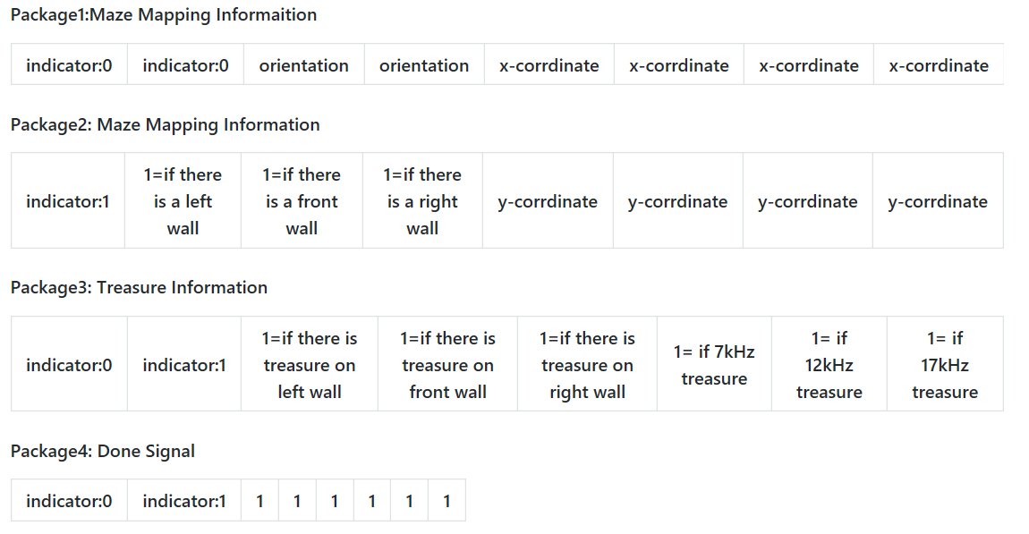
Package format that the Robot sends the Base Station:
Radio
The radio portion of the robot is almost the same as in Lab 3, except since we did not actually take apart our 8-bit string, we did it here instead. In addition, we came up with a new syntax with indicators to delineate what type of information is being sent in the 8-bit string. We divided the data into two package. To decode the 8-bit data, we use the AND with 10000000 to extract the most significant bit, if it is package 1, then we continue to use AND to get the orientation and the x-cord, if it is package 2, then we can get the data of three wall treasures and y-cord.
Below is a test video, we manually set the the wall and the position, it shows that two arduino can transmit the data successfully.
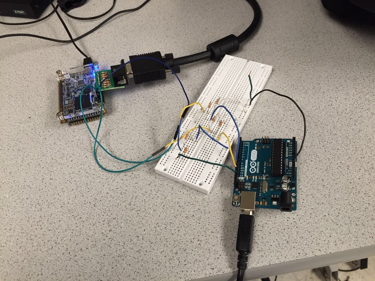
SPI
After the data was transmitted to the base station’s Arduino, we need a SPI transmission interface for the FPGA to read in the data and knows where the robot is and what is around it.
There are 3 outputs from the Arduino: clock (sck) from pin 13; master out slave in (mosi) from pin 11, and chip select (ss) from pin 10.
With a voltage divider (5v to 3.3v) in between, we connect sck with GPIO_0_D[28], mosi with GPIO_0_D[24], and ss with GPIO_0_D[26].
We would use the Arduino to send data with the SPI library with the following function:
void setValue(int value)
{
  digitalWrite(ss, LOW);
  //SPI.transfer(0); // send command byte
  SPI.transfer(value); // send value (0~255)
  digitalWrite(ss, HIGH);
  SPI.setClockDivider(SPI_CLOCK_DIV128);
}
with the value being the decimal value of the 8-bit data we’re transmitting per time.
On the FPGA side, we read in the data using the following code:
reg [7:0]  data_receive;
reg [7:0]  data;
wire        ss;
reg [2:0]  idx;
wire [7:0] arduino_clk;

assign ss = GPIO_0_D[26];
assign arduino_clk = GPIO_0_D[28];

initial begin
  	idx = 0;
  	end

always @ (negedge ss) begin
  	    idx <= 0;
        	  data <= 0;
        	  data_receive <= 0;
  	end


always @ (posedge arduino_clk) begin

        	  data[idx] <= GPIO_0_D[24];
        	  if(idx<=6)
        	  idx <= idx + 3'b1;
        	  else
        	  idx <= 3'b0;


  	end

always @ (posedge ss) begin

  	    data_receive <= data;


  	end
Testing with Arduino sending data from 0 to 255 and show the data received by the leds on fpga board:
Drawing the Maze
Introduction
The course required us to use an FPGA and Verilog to output a visualization of the maze to a display over a VGA connection. A VGA signal can be viewed as a 640 by 480 pixel space where each pixel is sent in order. This order starts with the upper-left pixel and scans horizontally until the end of line, where it jumps back to the left side on the line below. These scans are performed with specific timings and a few sync connections while the color is transmitted over separate analog RGB data. Luckily Verilog code for doing this on the FPGA was provided so we could just focusing on writing code that converted the requested X and Y pixel data into the correct color.
We recognized that the maze is a 5x4 array of identical cells and used this to divide our code into two parts: the decoder and the render. The decoder’s function was to convert the requested X and Y pixel and localize it into which maze cell it belonged too or whether it was in the background. The localization process was to extract the relevant map data and shift the global X and Y positions into those relative to the upper right corner of the cell to be displayed. This allowed us to use a single cell renderer to display the entire maze. The render’s job was to use the map data and the relative decoder and decide which color to output.
Decoder
if(X >= (`X_SIZE*10'd0 + `X_OFFSET) && X < (`X_SIZE*(10'd0+10'd1) + `X_OFFSET) && Y >= (`Y_SIZE*10'd0 + `Y_OFFSET) && Y < (`Y_SIZE*(10'd0+10'd1) + `Y_OFFSET))
    begin
      XOFF <= (`X_SIZE*10'd0 + `X_OFFSET);
      YOFF <= (`Y_SIZE*10'd0 + `Y_OFFSET);
      CELL <= MAP[7:0];
      if(rpos == 5'b00000)
        RBT <= {roth,5'b11111};
      else
        RBT <= {roth,5'b00000};

    end
…
else
    begin
      XOFF <= 10'b1111111111;
      YOFF <= 10'b1111111111;
      CELL <= 8'b00000000;
      RBT <= 8'b00000000;
    end
  end

endmodule
Figure 1: Truncated version of the decoder code.
The maze was visualized as 5x4 cells that were dimensions X_SIZE and Y_SIZE and the entire maze was offset from the corner by X_OFFSET and Y_OFFSET. This allowed us to center the maze on the screen easily and scale the X and Y dimensions to get relatively square cells. This was important as the displays typically displayed equal dimensions as rectangles since the pixels were rectangles not squares.
It then passes the current requested X and Y pixel data through as cascade of if-else statements to find within which cells extents the pixel is in. If it wasn’t in a cell than the output variables were set to sentinel values to indicate such. Otherwise, once the current cell was found, the offset outputs would be set to the current pixels upper left corner so relative coordinates can be used in the renderer. Additionally, the current map data would be placed in the CELL output byte and the robot position would be tested to see if the robot should be rendered in the current cell. All of these outputs were the inputs to the cell renderer.
Renderer
always @ (posedge CLK)
  begin
    if(XOFF == 10'b1111111111 && YOFF == 10'b1111111111)
    begin
      COL <= `BLACK;
    end
    else if(xrel >= 0 && xrel < `X_SIZE && yrel >= 0 && yrel < `Y_SIZE)
    begin
      ...
             ...
      // north wall
      else if(xrel >= `W_WALL && xrel < `X_SIZE-`E_WALL && yrel >= `ZERO && yrel < `N_WALL && NORTH)
        COL <= `COL_WALL;
          ...
     ...
      // background color
      else
        if(TREASURE == 2'b01)
          COL <= `RED;
        else if(TREASURE == 2'b10)
          COL <= `GREEN;
        else if(TREASURE == 2'b11)
          COL <= `BLUE;
        else if(COLOR == 2'b01)
          COL <= `COL_VIS;
        else if(rcnd)
          COL <= `COL_RBT;
        else
          COL <= `WHITE;
    end
    else
      COL <= `COL_UNDF;
  end
endmodule
Figure 2: A listing of the truncated renderer code.
The render takes the input data and provides a one to one mapping of relative pixel to an output color without any double counting. First if the offset values were set to the sentinel values then the background color BLACK was used to fill in the empty space. Else, if the requested pixel was inside the cell dimension then the color would be mapped according to the map data otherwise it would be set to an undefined marker color to indicate an error.
The renderer would first test if the pixel belonged to any feature such as a wall and if the wall was to be rendered then the color would be set to the wall color. Otherwise the color would be set to a background color RED, GREEN or BLUE if there was a treasure and special colors to indicate that the robot was currently in the cell or that the robot had previously visited the cell, these were useful for algorithm testing purposes. Finally, if the cell had no special background then a default of white was used.
Video of operation
The following is the vedio of the Monitor displaying the different squares and the walls. The grey squares are blank space the and the colored ones are the ones that contain the treasures.:
Next Step:
We have have the milestone in components and be plan to put all our parts together to get a rea-time update while the Robot navigates the maze.